HF Beam Antenna Installation
Updated
14-Dec-2008
10:40
[back to W1TR HF Tower and Beams]
[back to W1TR Antennas and QTH]
Antenna Installation (Nov 2008)
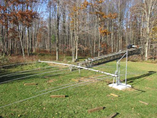
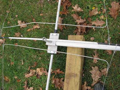
I got the C4SXL from John, N1PGA, who thought it had a home at his QTH but then he changed his mind. I started assembling the antenna, 2 elements each on 40, 20, 15, 10… I guess I have all the pieces! All the U-Bolts were replaced with new stainless. Here it is shown resting on tip of the tilted over.
Linear Loading Renovation (Nov 2008)
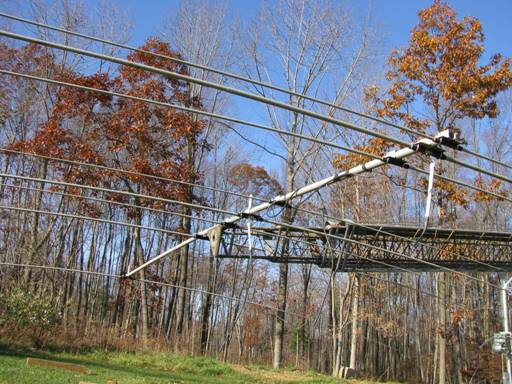
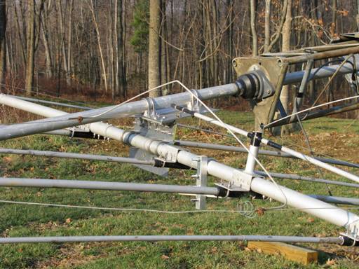
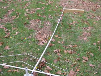
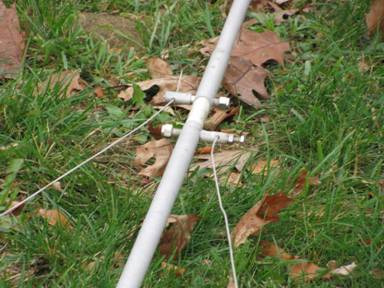
This is the 40 meter linear loading mechanism, which is kind of like a giant one turn loading coil inserted in the element about 8 feet out from the boom (reflector shown). Thanksgiving weekend I finished renovating the linear loading by replacing ALL the aluminum wires with stainless steel cable (3/32”) stainless cable clamps, and stainless bolts to connect the wires to the elements. Some of the old bolts were seized up and broken so this had to be done. After renovation, the 40 meter antenna was resonant about 6.5 MHz so I had to totally retune the elements by adjusting the linear loading wires. This is done by adjusting the distance from the boom of the large jumper elements shown above. I disconnected the jumper between the two halves of the reflector, and disconnected the hairpin matching coil and the balun at the driven element feed point and independently tuned these elements using the MFJ 259 Antenna Analyzer. Near the ground, I adjusted the reflector to 7.0 MHz and the driven element to 7.1 MHz. When the antenna got into the air at 50 ft, the antenna appeared to be resonant at 7.225 MHz with an SWR of 1.1 to 1 and 2:1 range from 7.160 to 7.300 (not bad, but I probably want it a little lower than that). I know that there are switching relays available for this antenna that will move it from the Phone to the CW part of the band, but I’ll investigate that after I try this awhile.
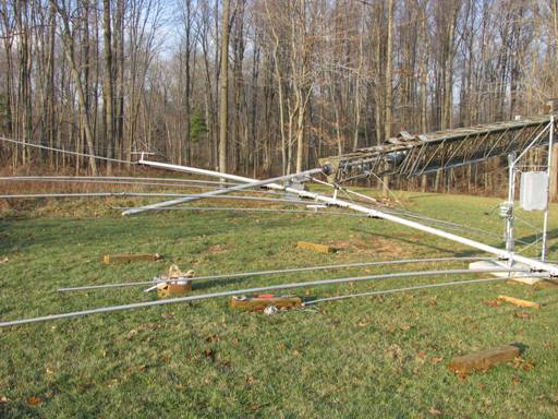
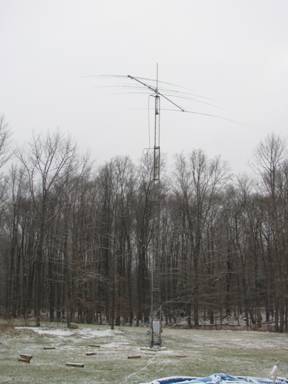
Antenna Raising (Dec 2008)
Once I attached the coax standoff arms and dressed the cables, it only took a short while to tilt the tower up and fasten the base bolts. Yes, the antenna is tilted about 10-15 degrees from horizontal due to inadequate clearance and/or alignment of the Saddle U-Bolts with the clearance holes in the Hanging Hinge Plate. Well… I guess I have to try tomorrow (Sunday, Pearl Harbor Day) or wait until next weekend to make any further adjustments. As you can see, none too soon to get this up before the snow flies since the first snow came last night!
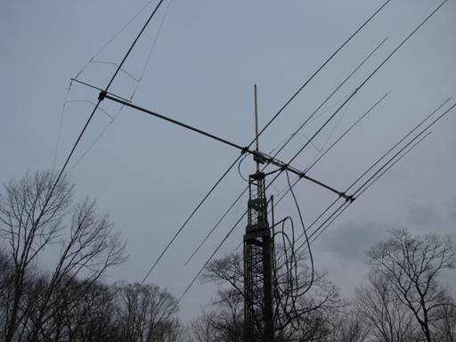
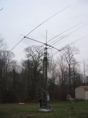
Yea!
The C4SXL Flys Again!
40 Meter Beam Tune Up (May 2010)
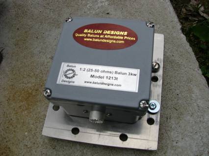
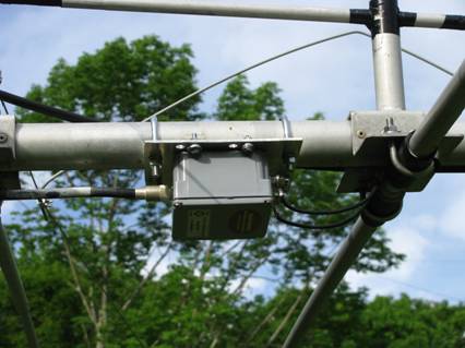
I have experimented a few times with the tuning of the C4SXL director and reflector to get a good match and reasonable pattern and forward gain. So far I am still working on it. I did decide to replace the 1:1 balun and the hairpin match with a Balun Designs 1215T 1:2 balun (25 ohms balanced to 50 ohms unbalanced). This enabled me to tune the driven element which measured out to about 25 ohms without the hairpin, to the proper frequency. I also used an electrical full wavelength coax between the antenna feed and the junction box at the base of the tower. This way I have a reasonable assurance that the MFJ 269 would read the real impedance of the driven element.
With the 1:1 balun still in the circuit directly feeding the elements without the hairpin match, at 72 feet I was getting a resonant (X=0, R=27 ohms) frequency of 7232 KHz. At 45 feet it was 7243 KHz. At 22 feet (tower all the way down) it was 7249 KHz. (HUH? I thought the frequency would become lower as the antenna got lower in height). With the tower tilted over it was 6927 KHz which was definitely lower! The R value varied from 27 to 32, not too much change, and the SWR was in the ball park of 1.8:1 just under 2:1. When I swapped the 1:2 balun in and the tower tilted over was X=0 and R=50, a perfect 1:1 SWR! And a range of plus or minus 150 KHz for a 2:1 SWR (maybe not optimal but useable across the entire 40 meter band without a tuner).
As of 23-May-2010, I still need to tune up the antenna a little better with the new balun. I tuned the reflector to be 100 KHz lower in frequency than the driven element (according to the advice of Mike K6MYC with whom I had a 40 meter (7155 KHz) QSO using the beam on 6-Nov-2009 at 0400z. I ran out of daylight and put the antenna back up, but the center frequency was 7000 KHz, a little low for my purposes. I will set it up to be about 7150 KHz to get both phone and CW within a 2:1 SWR.
The next project for this antenna will be a switch box with some series inductance that will allow me to set the phone frequency at 7200 KHz and the CW for about 7050 KHz. I think I can put the new balun and the relay with the series inductors all in the same box which is about twice the size (length) of the one shown above.
All I need then is to add the 17m element modification described in a recent QST article.