VHF Tower Electric Winch
Updated
11-May-2019 17:01
[back to W1TR Antennas and QTH]
I would like to thank W4ABC for posting this idea on his web, using the Harbor Freight engine hoist upside down.
I had been looking at this hoist and others like it but was unsure whether to proceed or not until I saw that he had it working already and there was little risk to trying it.
Manual Winchs on the Tristao HG52SS Tower
Before and After
These are the original manual winches that come with the Tristao HG52SS crank-up tower and the Hy-Gain LM-470D tilt-over accessory that I used to raise and lower the 52 foot tower.
In 2011, I decided that I was getting too lazy to manually crank up / down this tower very often having been spoiled by the larger LM-470D tower which comes with a motor as its standard configuration.
During bad weather, I often park my towers at half height to reduce the risk of damage. Antennas are easily replaced but not towers!
Often I have avoided raising the tower all the way up for the Monday night VHF and UHF nets because of this inconvenience, and have even operated a VHF contest or two with it at half mast.
This hoist is indeed the solution to this laziness!
Much later in 2018, I became even more lazy and decided that cranking the manual host to tilt-over the tower was too much work, so I added a second electric winch for that purpose.
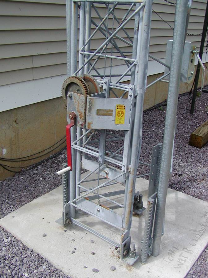
Telescoping Electric Winch Installed 28-Oct-2011
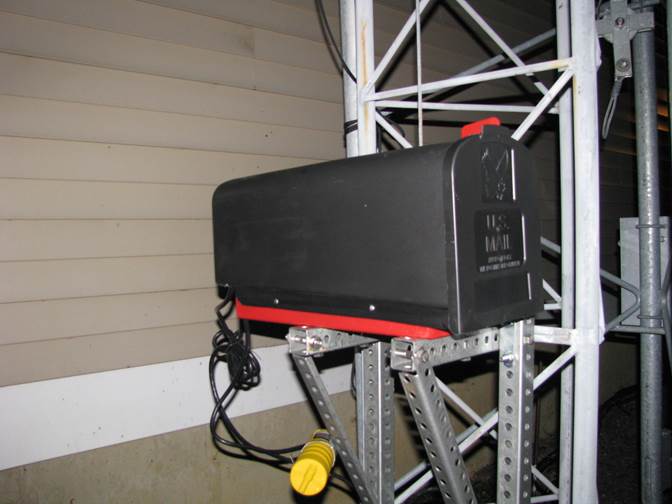
This looks like a mailbox, but under the hood is a hoist to replace the manual winch that originally came with the tower.
The plastic mailbox (available for $10 at Home Depot) is used as a weather shield since the hoist is not intended for outdoor use and must be protected.
Hoist on Mounts Without Weather Shield
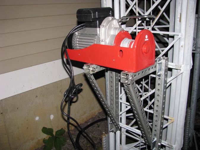
With the mailbox / weather shield removed, it looks more like a winch.
It is in fact a Harbor Freight 650 pound hoist mounted upside down.
A hoist should be used for this application instead of a winch because of the difference in meaning of the ratings.
A winch is rated to pull a certain amount of weight horizontally, like pulling a boat out of water or a car out of the ditch.
A hoist is rated to lift, lower, and statically hold a heavy object such as an engine from a car, etc.
The entire HG52SS tower weighs 550 pounds, and if it is assumed that the mast and antennas weigh 100 pounds, the entire weight of the tower and antenna system can be lifted by this hoist.
However, only the top 2/3 of the tower will be lifted giving about a 150 pound safety margin on top of that already built into the hoist ratings.
Another View From Below
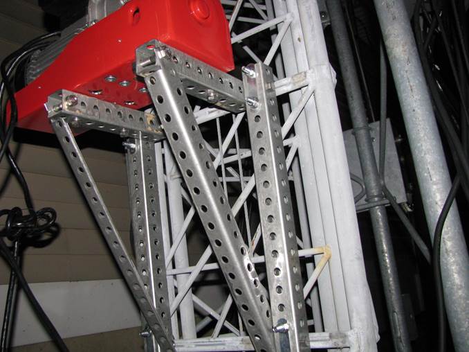
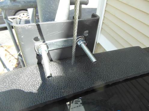
The two mounting brackets are constructed from square and L-shaped steel stock with holes on 1 inch centers (available at Home Depot).
Stainless Steel bolts fasten the parts together, and 2 inch centered U-Bolts fasten the vertical members of the bracket to the tower horizontal cross members.
The original bolts in the bottom (I mean top since it is upside down) of the hoist frame had to be replaced so they would be long enough to also go through the 1 ½ inch square steel stock.
A notch in the L-Shaped stock had to be cut to make sufficient clearance for bolting the diagonal member to the horizontal member.
Note the two drilled and tapped holes in the side of the hoist frame used to bolt the weather shield onto this frame.
There are two more hidden on the back side.
The four-in-a-line recessed hex head nuts in the bottom of the hoist frame are used to fasten the hoist to the frame.
To attach the tower pull-up steel cable to this hoist, the existing cable must first be removed.
This is done by first unwinding the existing cable and then detaching the hoist mechanism from the frame by removing the four recessed hex head bolts in the bottom of the frame.
There is a bearing to the right of the frame that more evenly distributes the force from the weight of the load.
The hoist mechanism must be moved to the left once the recessed hex head bolts are removed and it will come out of the frame. T
here is a plastic retainer or nut that may come loose from the right end of the hoist spindle, be careful not to lose this, and be sure to replace it when reattaching the hoist mechanism to the frame.
The steel cable is attached to the spindle by a small wedge that is inserted in a steel cable loop (it will be obvious when you see it).
Weather Shield Made From Plastic Mailbox
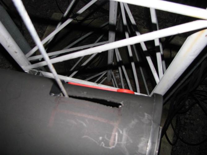
Note the horizontal slot cut in the top of the mailbox weather shield so that the steel cable can play freely with it attached to the hoist frame.
To facilitate removal / replacement of the weather shield, the back side of it is cut
(see the black electrical tape covering this cut just to the left of the steel cable)
so that it can be fit onto the hoist with the cable installed.
Note also that the bottom of the mailbox also must be cut out so that it can be mounted on the hoist frame.
Secondary Weather Shield Made From Mailbox Bottom
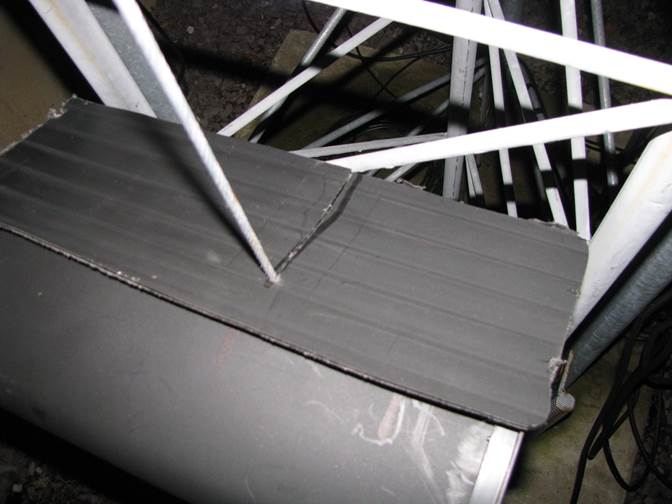
The bottom cutout piece of the mailbox is used as a secondary weather shield when the hoist is not in action. A slot is cut and a hole drilled into this left over piece of material to further prevent rain and debris from getting into the hoist. This should be removed when using the hoist to raise or lower the tower.
The “Smoke Test”
Whenever making the first test of a piece of equipment or machinery, there is often a bit of anxiety or hesitation as to whether it will work properly or blow up in your face! I held my breath, plugged it in, and pressed the UP button and low and behold the tower lurched upward. Similarly pressing the DOWN button lowered it. This hoist is pretty speedy and I would probably prefer a slower travel rate, but it has sufficient power to lift the tower surely and steadily, and I’m confident that I will get many good years of service out of this installation. I will also be less likely to skip raising the tower for those Monday night nets and occasional contests with this new convience. I really love to work hard one time only so I can be lazy for the indefinite future!
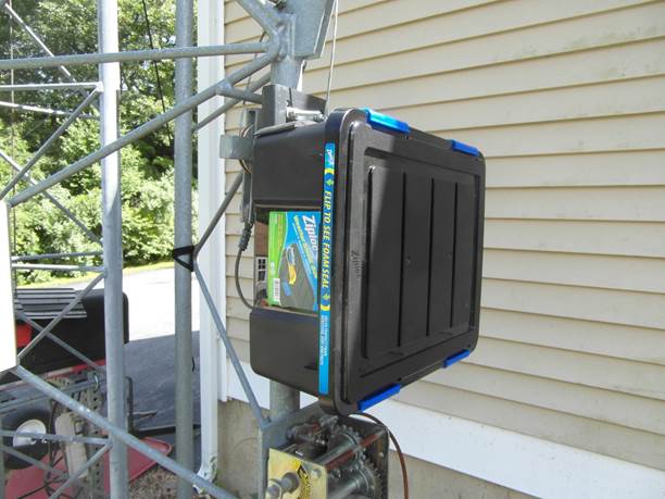
TiltOver Electric Winch Installed 24-Jul-2018
Having become even more lazy, I decided to install an electric winch for tower tilt-over.
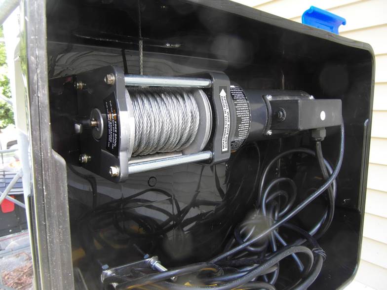
This unit is a Harbor Freight 1500 pound 110 VAC winch item 61672 / 96127 in the August 2018 catalog.
I had to make some modifications in order to use it in my installation.
The mounting plate which runs parallel to the winch body was removed along with the rectangular flange that frames the opening for the cable and hook.
The mounting plate was oriented backwards and at right angles to the winch body to be parallel with the vertical member of the tilt-over accessory for the tower on which it will be mounted.
The original mount was a triangular pattern of 3 holes and bolts. The new pattern was an almost square rectangular pattern.
This is easy to do with a simple drill press (also Harbor Freight) and a set of drills.
The original bolts were 5/16 inch, but I upgraded them to 3/8 inch, with the usual washers, lock-washers and bolts, mainly because I had an inventory of them available from other projects!
The second modification was to use a hack saw to remove the large hook at the end of the cable which I didn’t need and which would not fit through the other fixtures already on the tower.
This left just a loop terminated cable ready for fastening to the anchor bolt on the tilt-over accessory.
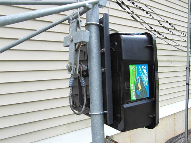
I enclosed the winch for weather protection in a ZipLoc weather proof box available at Walmart.
Time will tell whether it will withstand the sunlight for years on end.
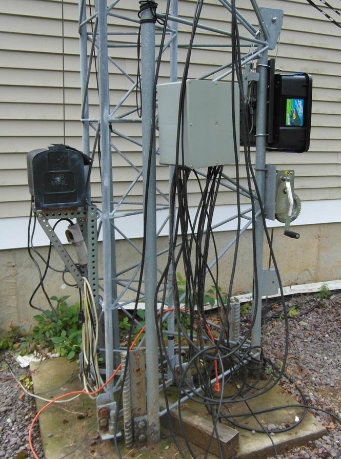
Overall Installation
The modified mounting bracket that is part of the winch was rotated 90 degrees backwards and remounted to the winch body.
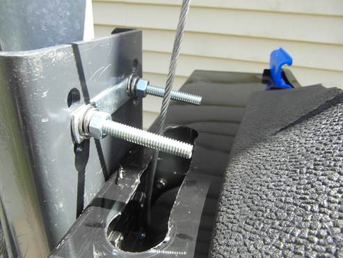
This mounting bracket was then drilled to accommodate 2 inch wide 5/16 inch diameter U-Bolts for mounting to the tilt-over accessory.
The top U-Bolt extends over the top of the Zip Loc weather proof box.
The lower U-Bolt extends through the bottom of the weather proof box.
Inside the Box
The ZipLoc weather proof box has sufficient room to store the 110 VAC power cable and the push button control for the winch when not in use.
A slot was made in the top edge of the box for the cable, using a 1 inch chassis socket punch for the ends, and a knife cut to create a rounded rectangle opening.
Weather Shield
The weather shield was made of a piece of ½ inch soft rubber kitchen floor mat (Walmart) that I had on hand from other projects.
A small drill hole was made and then a slot was cut to allow the weather shield to be mounted to the weather proof box when the winch is not in use.
This same material was used to replace the weather shield on the telescoping winch.
Mechanical Stress Analysis
The winch is rated at 1500 pounds.
The tower weighs 500 pounds and the antennas maybe 100 for a total of 600 pounds.
If the tower is lifted from the far end and the near end is on a hinge bolt, the force would be 300 pounds vertical.
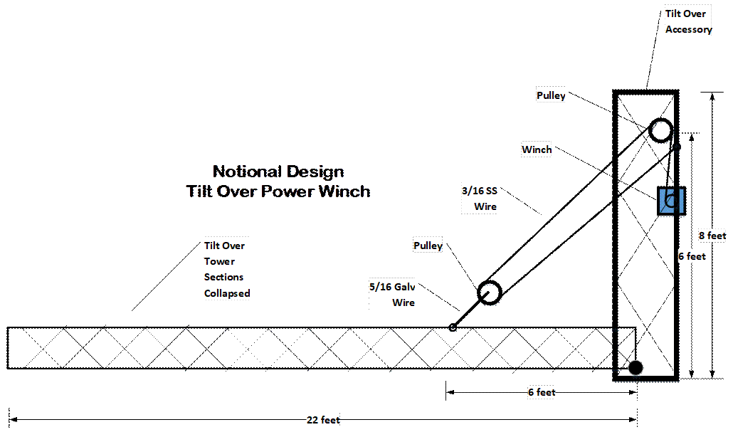
Since the tower in collapsed configuration is 22 feet and the point of attachment of the pull-up cable is at 6 feet, the vertical lift weight will be about 1000 pounds.
Since the force will be at 45 degrees worst case, then the force will be about 1500 pounds.
There is a 2 to 1 mechanical advantage pulley in the lift mechanism, making the approximate force needed from the winch of about 750 pounds.
This is within the ratings of the winch and cables.
The cable was upgraded in May 2019 for a larger safety margin.
Smoke Test
The installation date was one of those hot humid sometimes sunny, sometimes raining days in mid-summer, and there were also some gusty winds, all of which making it not a great tower working day.
The smoke test was made mid-August 2018 when the tower was lowered for maintenance.
The G-600RC rotor was changed out for a G-1000 DXA (450 degrees rotation), a larger 6m beam (17 foot boom) replaced the A505S (12 foot boom), 222 MHz and 902 MHz beams were added to the tower.
Storm Damage
Unfortunately, in Nov 2018, a windy Northeaster storm broke the 902 MHz beam mount, and blew off the 6m beam balun.
This was repaired in May 2019, replacing 8x32 bolts with ¼ stainless steel bolts, and the 6m balun was more securely fastened.
Details of the Tilt Over power Winch Design
The tilt over power winch design requires about 25 feet of 3/16 inch diameter stainless steel wire rope.
18 feet for the diagonal 6 feet x 6 feet, 2 feet for the distance from the pulley to the winch, and 5 feet extra to wrap around the winch.