VHF Tower Installation
Updated
25-Nov-2010
17:19
[back to W1TR Antennas and QTH]
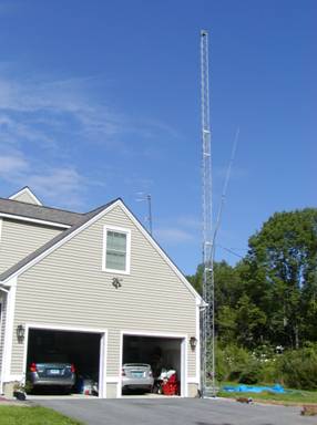
Tower Installation (Early Aug 2008)
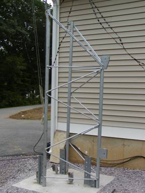
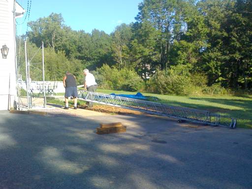
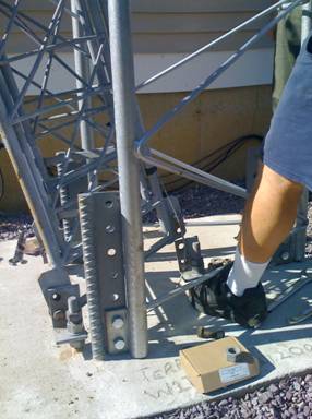
After waiting for the concrete to cure, the TA-70 Tilt Over
Accessory was dragged by me (yeah I actually did some work to put up this
tower!) over to the concrete base and installed on the mountings. Then I got some more help from Frank KB1LKB
to move the tower into position on the hinge bolts of the tower mounts.

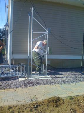
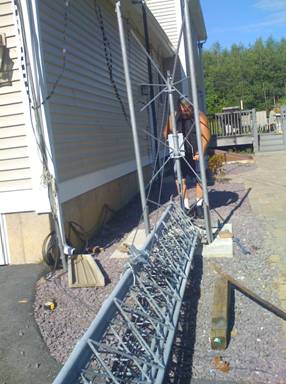
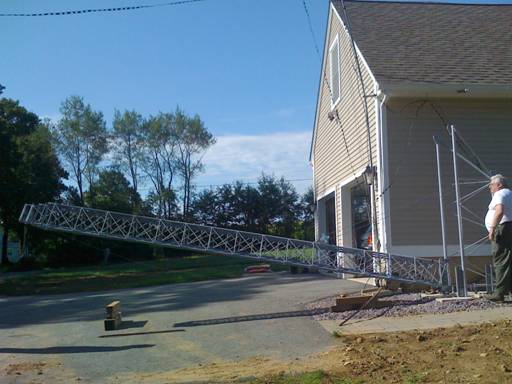
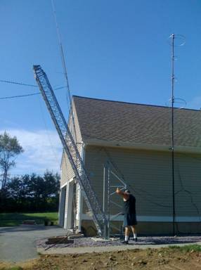
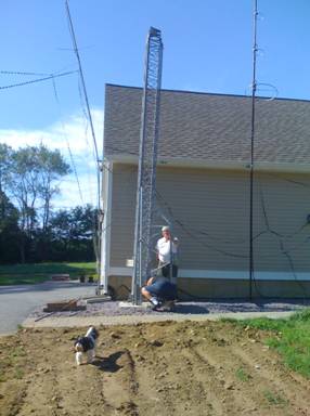
First Tower Tilt-Up (Early Aug 2008)
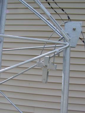
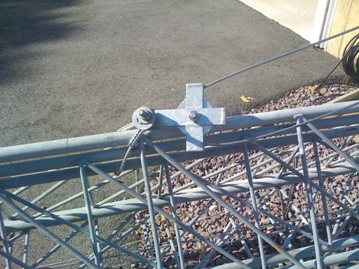
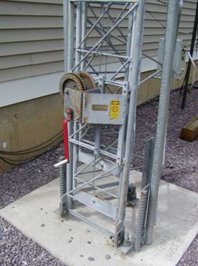
After mounting the tower on the hinge bolts, we tilted the tower up without any antennas, masts, or rotator to see if everything fit together, and made adjustments to the tower mount hardware. The winch that comes with the TA-70 has a 2500 lb capacity and has a brake which prevents the tower from lowering without cranking in the downward direction. The steel rope goes through a pulley near the tower which is attached to the tower using a small loop of steel rope and bolts to the pulley giving a 2:1 mechanical advantage. Newer versions of the LM470D tower, for which this hardware is intended, have an ear welded to if for bolting the pulley direct to the tower.
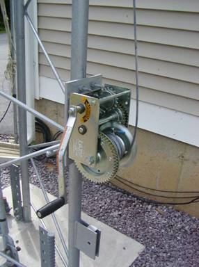

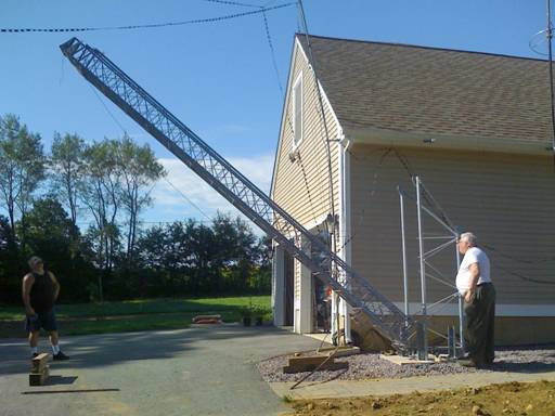
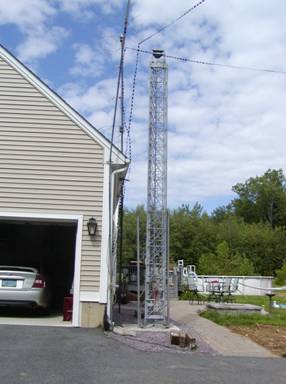
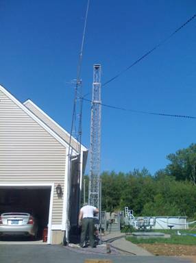
First Tower Crank-Up (Early Aug 2008)
After tilting the tower up and installing the remaining mounting bolts, we cranked up the tower without any antennas, masts, rotator, to see if it was in good operating order (it was). I may replace the crank-up winch with a motorized one since I’ll be using this feature a lot to keep the tower’s profile low during storms and high winds that occur on top of this mountain!
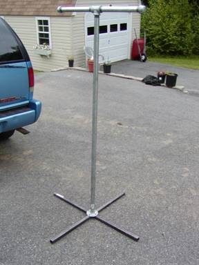
Tower Safety Stand
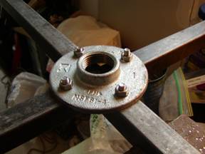
When working on the tower and/or antennas, a safety stand is used to support the tower a when tilted over a few feet off the ground. The safety stand is made of 1 ½” OD steel pipe. The TEE at the top is made from two 1’ pipe sections, a TEE section, and end caps (probably not really necessary). The Base is made from two 1” x 1” x 3’ steel square irons with a notch created in the center of each using a hack saw. These legs are fastened to a pipe flange section with screws.
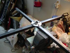
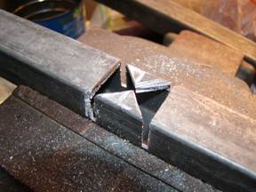
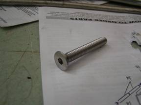
The detailed construction of the base is shown below. I used two hack saw blades to make wide cuts in the square steel material, and then diagonal cuts so that the pieces would fit together when placed at right angles to one another. Holes to match the pipe flange were drilled and flathead screws were used to minimize any indentations in the pavement of the driveway.
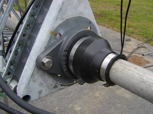
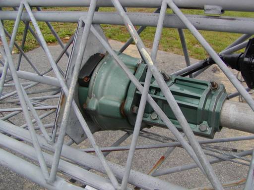
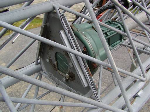
Thrust Bearing Weather Boot
I first installed the TB-2 thrust bearing on the top of the tower, but had to drill new holes since the old ones didn’t fit.
I used a rubber 2 inch to 3 inch pipe converter with hose clamps to act as a weather boot for the TB-2.
Rotator and Mast Installation
Then I figured out how to put the rotator plate inside the tower and managed to thread the Yaesu G-600RC rotator inside the top of the tower and down to where the rotator plate was
(yeah, it needed new holes as well!). I used a 20 ft thick wall aluminum mast.
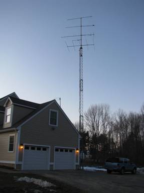
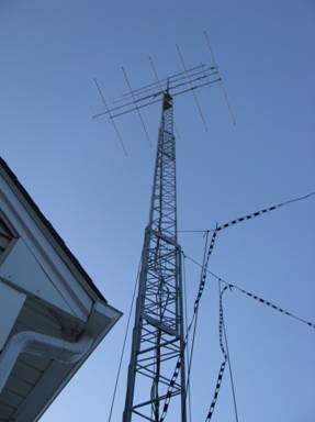
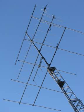
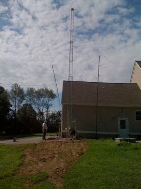
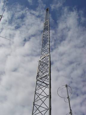
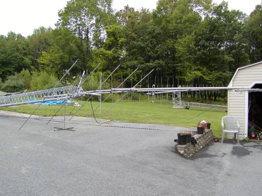
Antenna Installation (Early Sept 2008)
Then I mounted the antennas from top to bottom (1296 MHz 45 el loop yagi, 19 el 432 MHz yagi, 15 el 2m yagi, 5 el 6m yagi, and then at the last moment decided to add the 4 el 2m FM yagi end mount). The next time it comes down for maintenance, I think I’ll add a 7 el 440 MHz FM yagi that is in the shed.

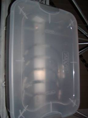
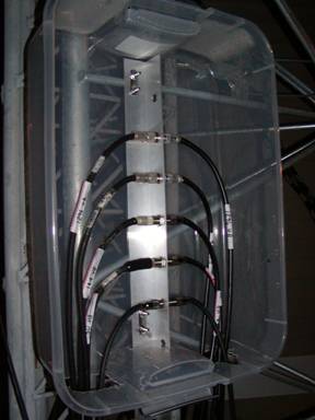
Weather Resistant Junction Box
Then I connected the coax cables to the antennas and the junction box, the ladder line support ropes.
To make a weather proof (well mostly weather proof) junction box, I used a plastic under-the-bed clothing container with a clamp-able lid (from Walmart $9, instead of a plastic NEMA box $200) and put necessary holes to feed the coax in from the bottom.
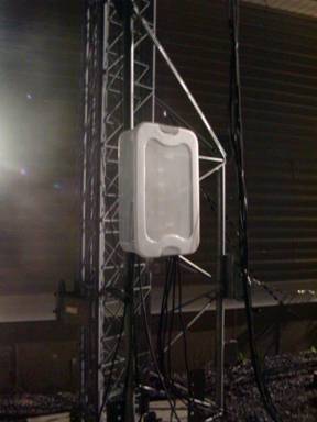
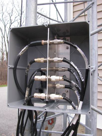
15-Nov-2010
These were replaced after two years when the sun and weather
made the boxes brittle so they broke apart. Some folks warned me that would
happen… they were right!
I used some PVC junction boxes 12x12x8 inches ($35 at Home Depot) and modified
them appropriately to feed COAX into them.
Shoulda done this to start with!!! ;-)
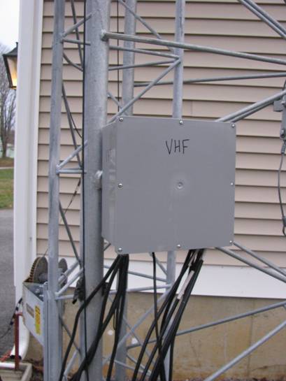
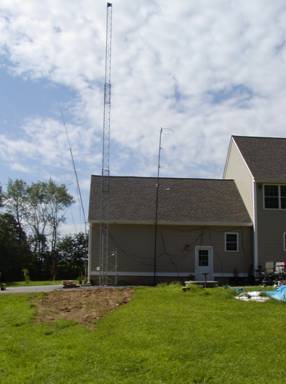
And.., up she went !